Upper Drum
Description This is the upper drum used in the SL-C9 / and SL-F1.

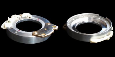
The drum shown above has a solid brass mounting plate and was prone to wear causing a sticking noise on rewind. Sony produced a replacement version made of a hard alloy identified by the absence of the brass mounting plate.

Upper Drum without brass
Newer version

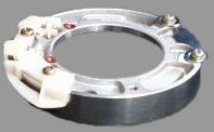
See also Complete Drum Assembly and Head Disk Assembly.

Symptoms A common symptom experienced on these machines is a thumping noise during tape rewind. Another symptom on some machines is that the tape 'sticks' to the drum. These are both due to wear on the upper drum assembly.

All models will produce poor pictures when the video heads wear out. The upper drum wears at about the same rate of the video heads. So whilst the heads are being worn down, the drum is also wearing down. This in effect, extends the lifetime of the video heads as the end result is that they remain in closer contact with the tape. When a new head is put into the machine, without replacing the upper drum, it protrudes more than normal from the drum. This causes slightly more wear to the tapes but more importantly causes the head to wear at a slightly increased rate. By replacing the upper drum at the same time, this eliminates this problem.

A second reason for replacing the upper drum at the same time as head replacement is that if the drum is worn, it can make aligning the new head more difficult (i.e. the output off the head pre-amplifier cannot be made 'square'). Using a new upper drum can help this situation.

The lower drum wears less than the upper drum and will probably only needs replacing after a second replacement upper drum is needed.

Fixing First examine the drum to see if it is excessively worn. Looking closely, you should be able to see the wear pattern of the tape across the drum. If you feel this with your finger and there is a significant ridge between where the tape passes and where it doesn't, then a new upper drum is needed.

N.B. If the video heads are worn, it will probably be necessary to change them at the same time, even if picture quality is currently ok. Replacing the drum without replacing the heads will mean they no longer protrude or protrude less from the drum resulting in a sudden drop in quality. It is probably best to first try without replacing the head as video heads are not cheap.

Remember to record a tape and play it back, as this is where tape head quality can best be determined (i.e. with recordings).

Replacing Accessories required: Centering jig.

N.B. Keep it carefully after replacing the upper drum, as it will be used again when replacing the guide arm assembly. (It does not accompany the guide arm assembly).

  1. How to remove the upper drum

    Note, while removing the upper drum, never move the hex socket head bolt (7). If it is moved, the gap in the rotary transformer must be adjuster later.


    How to remove the upper drum

    1. Unscrew two screws (1) and remove the damper assembly.
    2. Unscrew two screws (2) and remove the guide arm assembly.
    3. Unscrew the hex socket head bolt (3) with an Allen key.
    4. Unscrew two screws (4), and remove the upper drum together with the upper drum mounting plate.

      Note: Be extremely careful not to touch the parts around the drum.

    5. Unscrew two screws (5), and remove the upper drum mounting plate from the upper drum.
    6. Unscrew two screws (6), and remove the tape path assembly.

  2. How to refit the upper drum

    1. Fit the tape guide assembly to the replacement upper drum with two screws (6).
    2. Refit the upper drum mounting plate with two screws (5).
    3. Lightly clamp the upper drum mounting plate installed to the upper drum to the drum supprt with two screws (4).
    4. Tighten hex socket head bolt (3) while holding the upper drum and the upper drum mounting plate tighly onto the drum support by hand.
    5. Firmly tighten two screws (4).
    6. Refit the guide arm assembly with two screws (2).

      Note: Don't firmly tighten screws (2), but allow the guide arm assembly to move horizontally.

    7. Insert the centering jig found in the box of the replacement upper drum between the guide arm assembly and the damper holder, and tighten screws (2) firmly. Remove the centering jig, and check the clearance between the guide arm assembly and the damper holder for uniform distribution.
    8. Refit the damper assembly with two screws (1).


    How to refit the upper drum (centering adjustment)

  3. Adjusting AFM rotary transformer gap

    1. Loosen hex socket head bolt (1) for the guide arm assembly without unscrewing, and lift the upper ring assembly slightly.
    2. Insert feeler gauge 1 into the gap in the rotary transformer, and push the upper ring assembly downward.

      Note: Take care not to tilt the upper ring assembly.

    3. Tighten the hex socket head bolt (1) while holding the upper ring assembly down.

      Note: Take care not to move the upper ring assembly while tightening the bolt.

    4. Remove feeler guage 1, and ascertain that feeler gauge 2 does not enter the gap. If it enters, start readjusting from process 1. on.


Adjusting AGM rotary transformer gap

Thanks to Mark Perry for supplying this information