The head motor fails to rotate, the unit therefore shuts down a short while after
        any transport mode (play, wind etc...) is activated.
    
    
        More often than not, the 
Hall effect sensor 
        on the motor fails and will need to be replaced. This is a small, 4 
        legged component that can be seen on the right hand side image in the 
        white area at the bottom. 
        
        
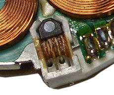
Hall effect sensors can be difficult to source, although with care, 
        spares from other models can be used (such as from Sanyo and Toshiba). 
        The part number sometimes listed appears to be the HTS-103A (per Sony circuit diagrams). 
        This though might be in error, the correct part could be THS-103A (seen on AliExpress).


The left 2 images are taken from a Toshiba drum motor.
        
The right 2 images are taken from a Sanyo VTC-M20 capstan motor board.


        In a few cases, the device can be made to work again by scraping away 
        the glue attaching the device to the board. This glue sometimes becomes 
        conductive shorting out the electrical signals. This is prone to occur 
        when the unit has been in a damp environment resulting in moisture being 
        absorbed by the glue. It is recommended to remove this glue. 


Hall effect sensor attached with glue


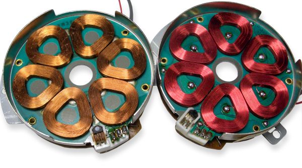
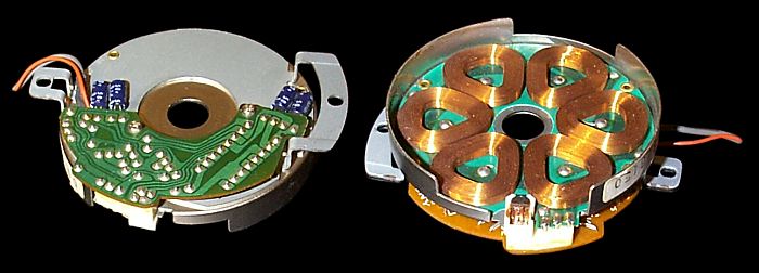
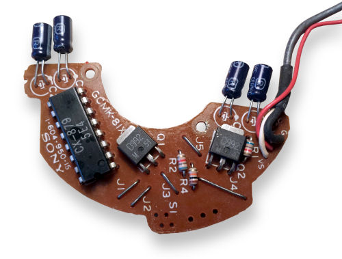
        The motor can also fail due to dry solder joints or when the 
        electrolytic capacitors dry up. The coils connect to the 3 pin block on the circuit board, and the hall effect sensor to the 4-pin block.


Hall effect circuit board
            
From left to right: Capacitors 1µF, 1µF, 0.1µF, 0.1µF all are rated 50v


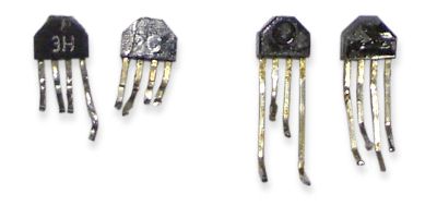
        If both of these approaches fail, it will be necessary to replace the 
        sensor with a second hand one taken from another machine. There are 
        various designs of hall effect sensors, but if it looks the same as the 
        Sony one, it will probably be compatible. 
        
        
These other units tend to have shorter leads which will need to be extended to 
        fit the Sony. A trick for fitting them is to use four 
        Teflon coated wires (wire wrap type) stripped bare for a suitable length 
        and passed through the four mounting holes on the drum motor board. Then 
        solder these to each of the device legs taking care that they are bent 
        to replicate the original pattern and clearance for the legs. Next draw 
        the excess wire back out of the holes to pull the hall sensor in place 
        and bend over each wire on its pad then solder / wriggle / break the 
        excess wire off. 
        
        
The correct orientation for fitting the sensor is with the lettering 
        side not visible.
        
        
To remove the board you need to (whilst having the machine in the best 
        orientation to do each task):
        
        
        - Take off the case bottom cover. 
        
        
- Remove the screws and flap out the small circuit board covering the reel 
        assembly/capstan and drum motors. 
        
        
- Remove the drum nut and magnet being sure to put aside the washer 
        beneath the nut and on the shaft under the magnet. 
        
        
- Top side of the machine, unscrew and fold out the tuner board.
        
        
- Disconnect the three wire drum motor drive lead (white three pin 
        connector with red lead and grey/white screened lead).
        
        
- Top of drum note the arm positions for the post guides then loosen the 
        left hand side (first guide and swing it away from the white upper tape 
        edge guide) .
        
        
- Swing aside the earthing bar out of the way of the drum and remove the 
        two screws and the white upper guide. 
        
        
- BEING VERY CAREFUL NOT TO TOUCH THE VIDEO HEADS OR LET THEM HIT ANYTHING.
        
        
- Get as much slack as you can in the remaining leads to the drum and 
        remove the three drum retaining screws with springs and washers.
        
        
- From above the machine carefully lift the drum assembly out of the 
        machine so you can access and remove the two screws holding in the drum 
        circuit board .
        
        
- Below the board open the white catch holding the cables and remove the 
        circuit board. 
        
        
- Assuming the machine is right side up, rest the Drum assembly back in 
        the machine (for safety of the heads) 
        
        
- Repair the circuit board by replacing the hall effect sensor. Remove all 
        the glue holding it in place. It is probably not necessary to reglue the sensor, 
        instead rely on lead tension to hold it in place. 
        
        
        Installation is the reverse procedure, again taking great care not to 
        damage the heads.


The left drum motor is faulty (note glue still on sensor.)
        
The right motor has been repaired. (wire colour makes no difference, the boards are the same.)


        Thanks go to Noel Higgins for supplying this information.