
Technical
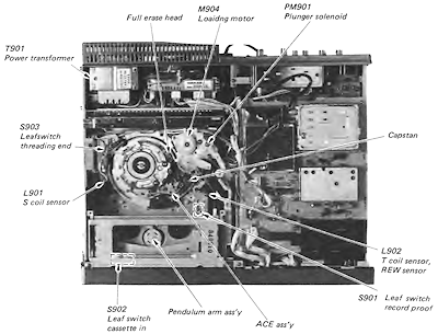
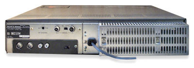 Rear view
|
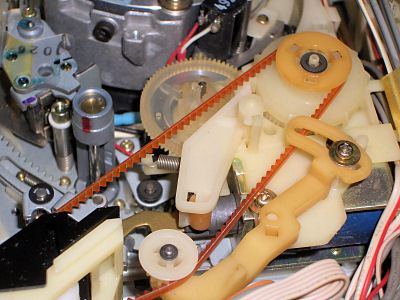
Cassette load/tape lacing mechanism designThe SL-F30 / SL-F35 mechanical design whilst the same in function was a simplification of the earlier SL-C series mono machines. The two part motor and solenoid plastic plates were joined into one and the metal drive selector arm (driven by the solenoid to direct drive either to the cassette tray or the load ring) was replaced by a plastic arm. |
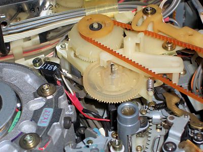
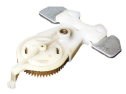 Pendulum assembly |
Stops in play or recordThis is becoming a more common problem these days. The first thing to check is that there is adequate torque on the take up spool. If there isn't much then the cause is usually down to two contributing factors.The first is the drive pendulum which can cease up and the second more serious factor, is wear on the reel motor bottom bearing. The pendulum is simple to replace but the bearing is moulded into the chassis and replacement necessitates that the entire chassis be replaced. One possible compromise is to fit a small piece of plastic into the bottom bearing to raise the rotor and allow it to move freely. Sony supply a repair kit for this purpose. |
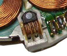 Hall effect sensor attached with glue |
No head rotationYou may find that the head drum fails to rotate. This is due to a problem with the Hall effect device on the head drum motor which is secured by a blob of glue. Full details on how to fix this can be found on the head motor page. |
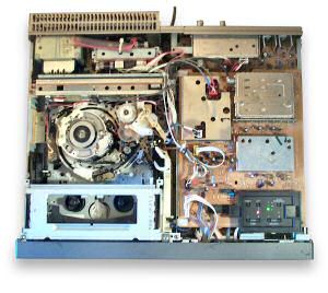 View inside |
Deck goes into rewindThis can be caused by failure of the tape end sensor. You can check this by unplugging the sensor at its socket on the PCB. |
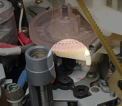
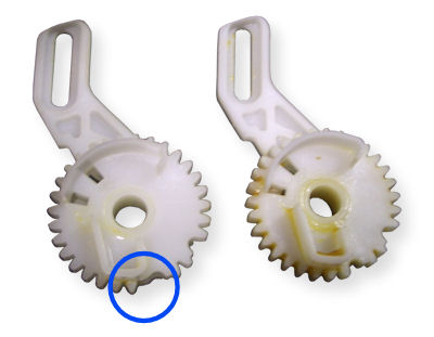 Broken gear (left)
|
Failure to load a tapeThe cassette carriage can fail to operate. This is caused by breakage of the plastic gears in the side of the mechanism. Often one of the teeth is missing.When this happens the faulty gears must be replaced and the mechanism correctly realigned so that the left and right side "tray arms" are at the same position relative to the front panel. This is done by releasing the plastic tab on the gear away from the motor side and selecting the correct mesh position with the teeth of the drive cog on rod which connects between both sides of the cassette tray. |
|
|
Power supply problemsThis VCR uses a STR1229A (IC001) at the heart of its power supply. If you experience PSU problems then this is the first thing to check. Be sure to check outputs 'onload' as the regulator can otherwise appear OK. |
|
|
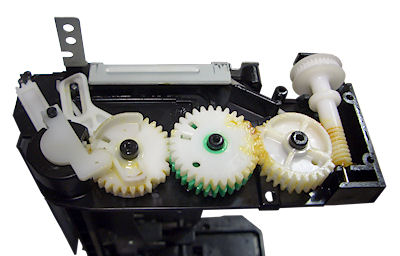
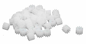
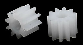
Loading gear and shaft repairThe loading shaft for the Sony has no official replacement but most times it can be repaired, unless the gear is in two pieces or a tooth has broken off. There are two approaches to solve this, either repair the broken gear, or purchase a similar gear and adapt it to fit.
In practice the diameter is sufficient and the reduced length does not really matter, just use super glue (or other suitable glue) to glue them to the shaft and protrude the shaft 1mm or so past the end.
See: RC-Toy-Car gears
If you don't need 50 then look for a smaller quantity but the price does not seem to change much. |
Quick fault guide
Please click on the button if you are able to contribute a solution to this list or would like to add to, or update PALsite's information on this model. Please note, questions will be removed.If you have a question about this model, please raise it on the chatpage.
| Fault | Solution |
|---|---|
| See also | Compare also with solutions from the SL-F35 tech page |
| Capstan motor speed varying in play | Check capacitor C316, if ok check IC303 (UPC455BC) |
| Grainy pictures in e-e mode | Suspect failure of the tuner BTS81 |
| Intermittent or erratic clock/timer operation | Check timer chip IC001 on panel TM57 |
| Intermittent or no lacing/unlacing | Check for failure of the shuttle block |
| Intermittent or no remote control operation | Check capacitor C5 for dry joints |
| No or poor capstan servo lock, tracking control inoperative | Check transistor Q345 for failure |
| No or poor playback pictures | Check capacitor C156 on panel YC15 |
| No capstan motor rotation, no playback record | Check resistor R406 for open circuit |
| No functions | Check for failure of IC602 (LA7205) on the SS34 board |
| No power on, clock OK | Check IC601 for failure |
| Poor servo lock on playback of own recordings | Check the control track head for contamination or wear |
| Preset tuner functions inoperative | Check for failure of IC005 |
| Stops after few seconds in the rewind a review modes | Modification: change resistor R2 to 33kohms (panel RD20) |
| Tape transport erratic / intermittent or no rewind / fast forward | Check the pinch arm assembly and the brake solenoid |
| Will not enter record mode, record tab safety switch ok | Check IC601 on the SS34 panel for failure |
| No picture | Check the drum |
| Squiggly patterning on playback until machine has warmed up | Replace all three 47µF and both 22µF capacitors in the Power Supply, with high quality parts rated at +85°C. |
| VCR does not record when you hit record | Make sure the record tab on the tape has not been removed. If it has, tape over the hole. |
| No display/picture output | Don't forget to check the head cleaning guide on PALsite. |
| Tape does not wind-up on tape reel bij playback | This is possible by a blowing fuse on the video print board, they are called PS001 or PS002 or PS003 and look like an ordinary transistor case. |
| wrong functions on the buttons on the front side | The remedy to solve this problem is, remove the front from the cabinet and replace all the buttons from the U-25 board, the buttons have by his age a resistance inside. |
| Start but not load the tape | Clean the switch of the right of the loader, if continuous equal verify IC'S connected at motor |
| Tape stops in Play, forward and rewind after a few seconds | Check/replace reel sensor board RD20 or RD21 photo diode. |
| No video or audio output | Check the AV board YC-31 on the underside of the machine for breaks in the board around the black plastic support plug in the centre of the board by flipping the board up and inspecting the brown surface where cracks are more obvious.
If tracks are broken on the track side use teflon coated wire wrap wire to bridge over cracks by connecting between component lands each side of the crack. Such damage has been noted on a number machines of this model that have been dropped. |
| Brake solenoid not functioning | Check connections to measure coil resistance. If no resistance measured then inline fuse is blown. Replace fuse.
If no replacement available then use 1/4W 10ohm resistor across the fuse to restore operation. |
| When tape inserted, tape thread ring operates instead of loading tape | Check capstan solenoid operation. If not working then measure coil resistance. If open circuit then replace coil fuse of the solenoid or the solenoid itself. |
| The Head Drum tries to spin, but it stops after a few seconds | Replace the HALL IC in the Drum Motor.
And remove ALL of the glue in the HALL Device. |
| Brake solenoid not working to shut off the VTR | Check the spring stopper it's mounted correctly. |
| Chewed tapes | If take-up reel drive tension is ok then examine pinch roller for worn bearing and replace if necessary. |
| Machine loads tape and threads around head then stops. No functions | Check that tape end sensor coil has moved into position. If not, check if the sensor coil spring mount has broken off. If so a 1.5cm length of wire made from a paper clip can be fashioned into hooks at each end to grab the spring and the other end of the paper-clip hook can be clipped into the existing hole on the base plate further away from the broken plastic mount and behind a plastic post. The end of the spring should end up at the same position as the original plastic mount was. (happy fixing - betaheaven.com) |
| Fluttering audio after press, rew and ffwd with picture search | Check for worn out tension band.
Replace the tension band, with a good one and re-adjust the back tension. |
| No function, No Clock. Only clicks when plugged in. Also applies to SL-F35 | Remove the front panel and access the display board. There are several capacitors that go bad and tend to leak. One is situated on the back side of the board (capacity around 220uF), one is right under the display (22uF) and one in the corner (470uF). There is also one small capacitor next to the IR sensor. If those capacitors go bad, they prevent clock module from functioning and the recorder doesn't perform the initial reset. This error is very often mistaken for the PSU failure. |
| The clock flickers or no clock at all. The machine will not start. Also SL-F35 | Remove the front panel and access the display board. On the left from the display there is an X-tal with a small ceramic capacitor labelled around 68J (68p). This is an oscillator. If the ceramic capacitor goes bad or changes value significantly (and it does), the clock flickers or won't start at all. |
| Machine enters REC-mode when pushing PLAY, STOP or EJECT | Suspect switches S1/S3/S5 on FU-25 board, clean and/or replace. Test for full continuity -these are connected on common line with REC(S7) switch, too high resistance on S1/S3/S5 activates REC-signal. |
| No colour on playback or recording | Replace trimmer for the PAL 4.43MHZ crystal for the colour carrier on board YC-31. This trimmer usually goes bad on the F30 and F60 |