Technical
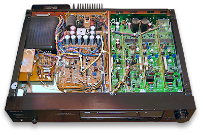
Inside view
|
Fault and repair guide
If you know of any solutions to problems with the PCM-701ES, please add them below.
|
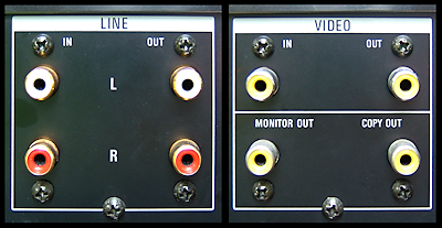
Rear connectors
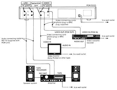
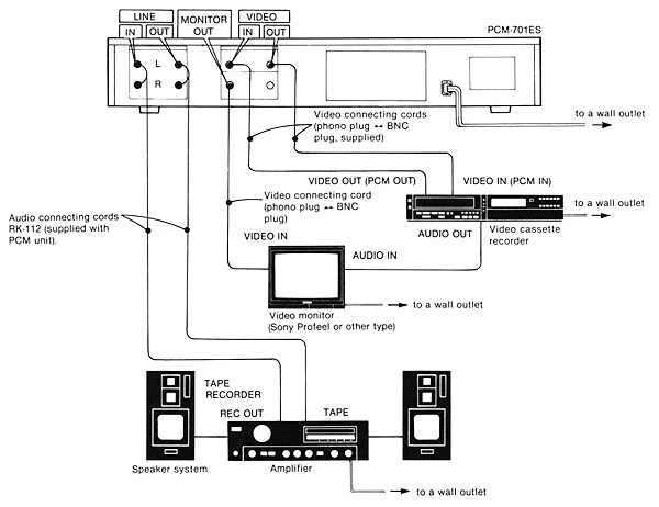
Typical connection set-up
(click to enlarge)
|
Connections
- LINE IN (phono input jacks for audio components)
- Connects with the tape outputs of an audio amplifier and the LINE OUT jacks of a stereo microphone amplifier.
- LINE OUT (phono output jacks for audio components)
- Connects with the tape inputs of an audio amplifier.
- VIDEO IN (phone jack)
- Connects to the video outputs of a video cassette recorder.
- VIDEO OUT (phono jack)
- Connects to the video inputs of a video cassette recorder. (Note: the output signal for this jack is cut off when the COPY button is set to ON.)
- MONITOR OUT (phono jack)
- Connects to the input jack of a Sony Profeel type video monitor.
- COPY OUT (phono jack)
- For digital copying. When making digital tape copies, connect the COPY OUT jack to the VIDEO IN
jack of the second video recorder and set the COPY button to ON. VTR 1 will be used to playback the recorded tape and VTR 2 will make the copy.
Note: The copy out jack can also be used for conventional recording of two tapes simultaneously. In this instance, leave the COPY button set to off.
CAUTION: Only use the COPY OUT jack for digital copying or for simultaneous recording using two video recorders.
Never make connections with the COPY OUT jack for normal recording using only one video recorder. If the COPY OUT jack is used as a
conventional video output, distorted sound reproduction will result.
|
Quick fault guide
Please click on the button if you are able to contribute a solution to this list or would like to add to, or update PALsite's information on this model. Please note, questions will be removed.
If you have a question about this model, please
raise it on the chatpage.
| Fault | Solution |
|---|
| IC401 replacement | When replacing IC401 (NJM5332P-A), add or delete C401, 401 depending on the marking signal on the IC. If '20', add C401, 402 (mounting). If '25' delete C401 and 402. |
| |